NOTE: This project deals with mains voltage. Perform all activities at your own risk.
So, I am a software guy, NOT a hardware person. I know enough to get by and have done a bit of soldering here and there but, I am certainly not an expert. However, as I was working on this project, I realized that many of the skills used for this project are skills I use in software development on a daily basis. So I want to take you on my journey of upgrading my dumb standing fan to be smarter.
Requirements
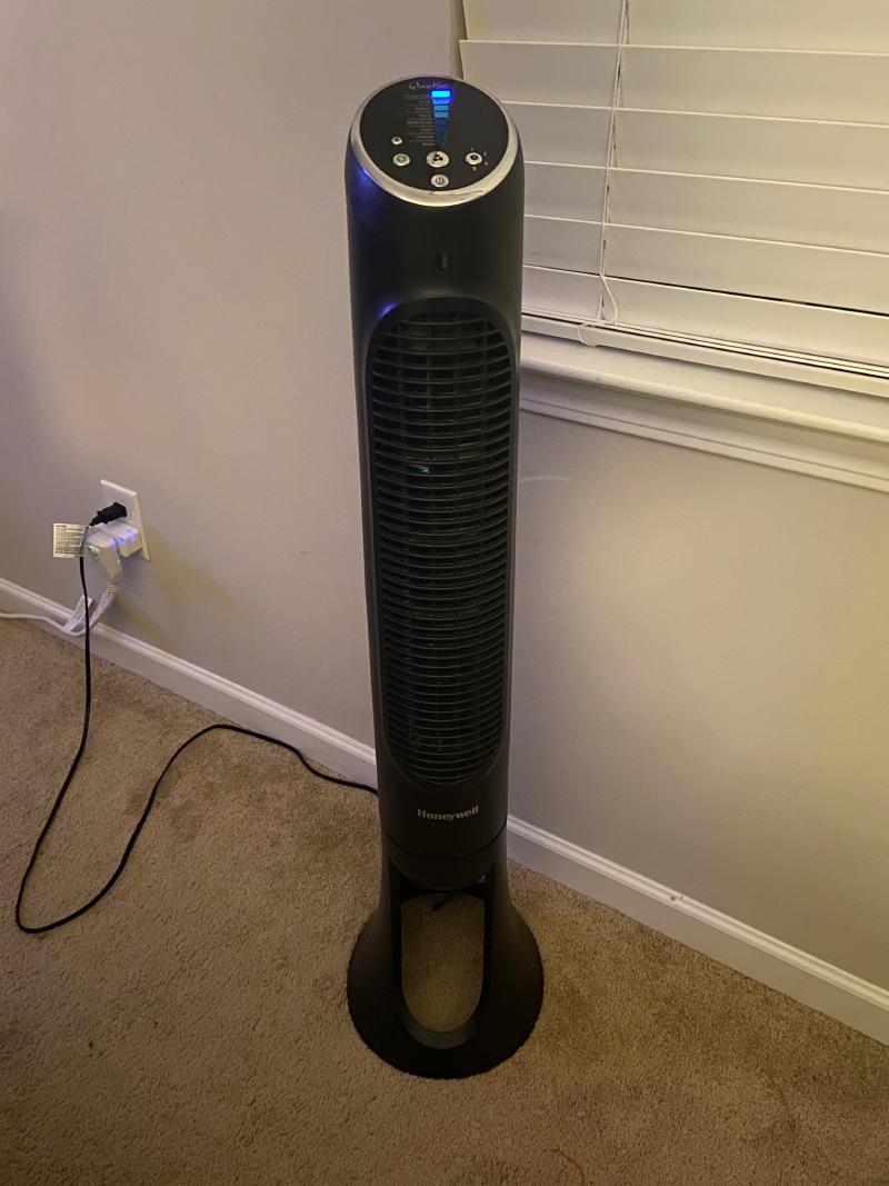
- A fan - Honeywell Standing fan
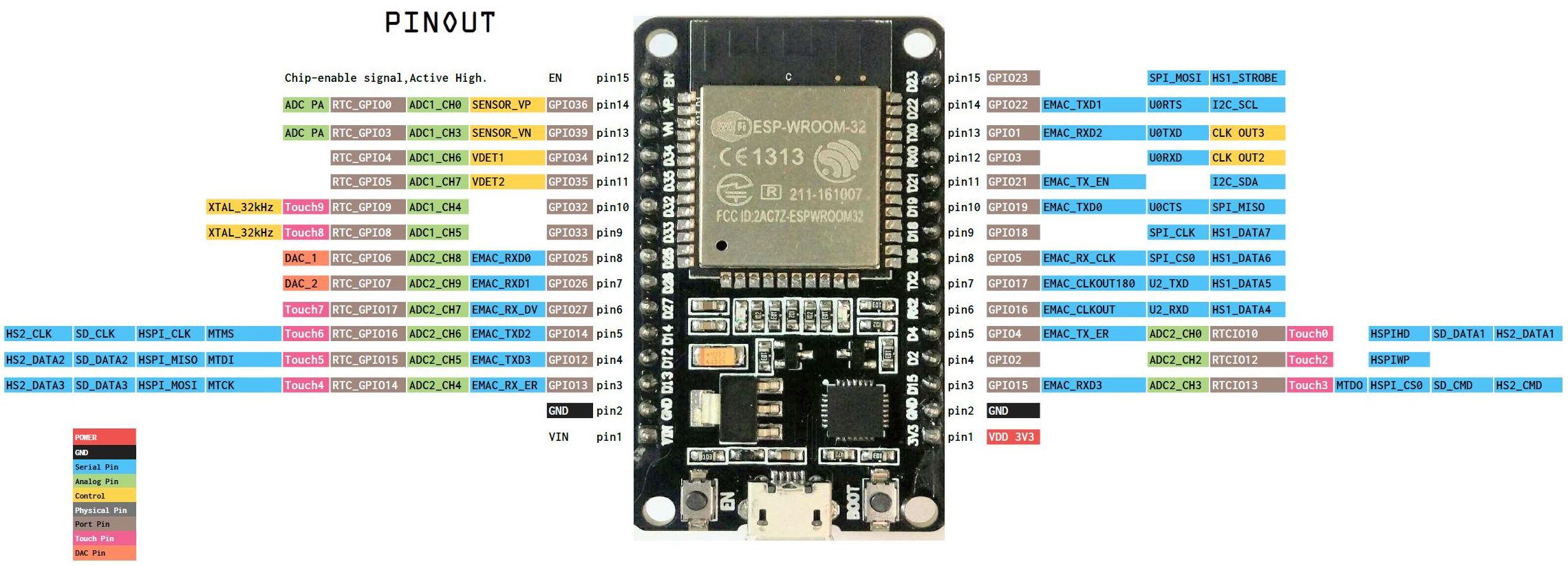
- A microcontroller - I used an ESP32
- A development environment - ESPHome (to connect it to Home Assistant)
- Some relays - As many as you need to control all the buttons you care about
- A soldering iron and solder
- A heat gun and some heat shrink
- A way to power the micro controller - I used a usb brick and a usb cable
Electrical
Discovery
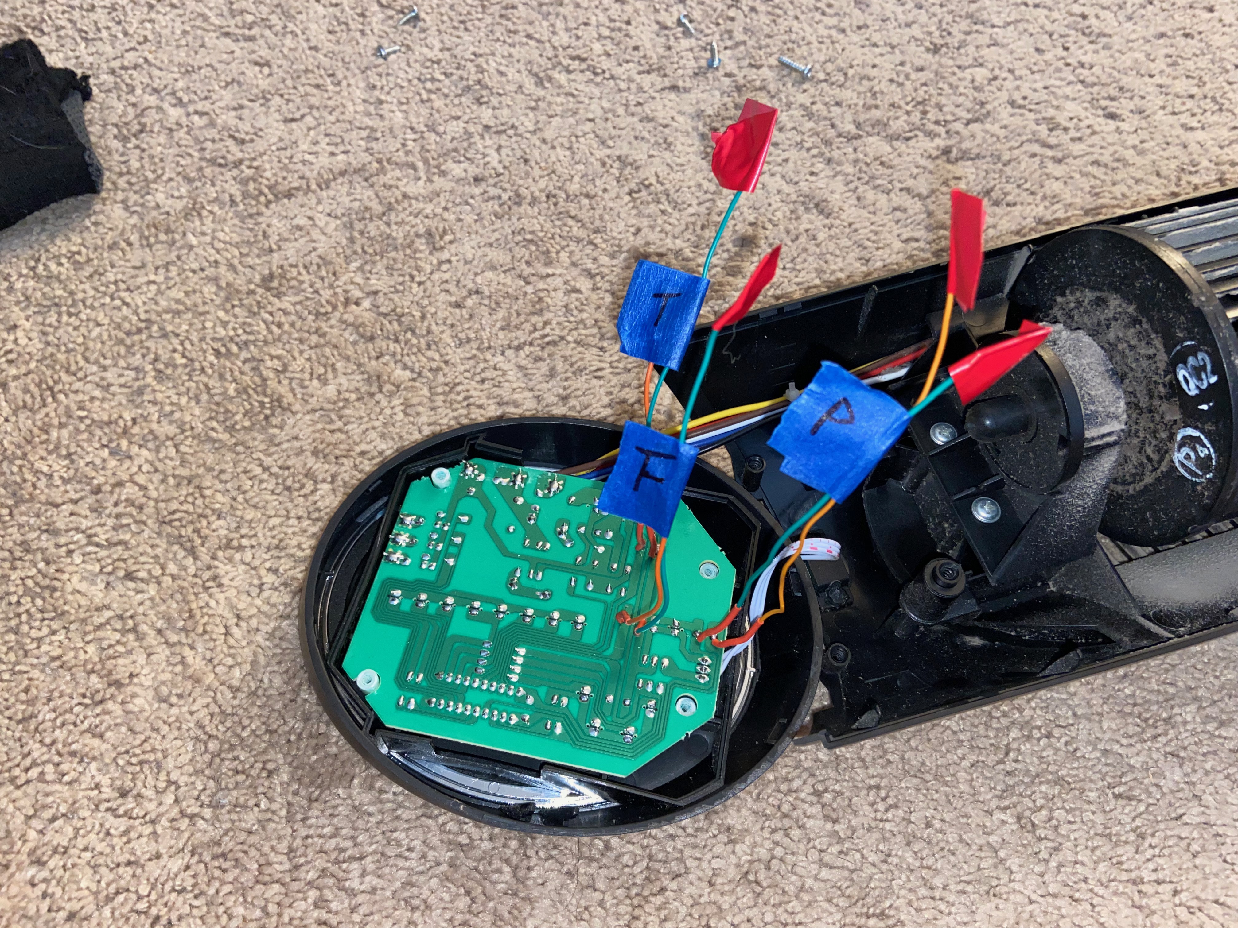
So it all starts with discovery. Meaning, take the thing apart. I could just have bought an off the shelf automated fan but, what is the fun in that? So, I got to pullin’ and it did not take long to find the control board. I found that they were using momentary switches to turn the fan on and off. I was a bit discouraged by that as I couldn’t know what the default state of the fan was. Was it already on? Or was the fan off?
Wire Up
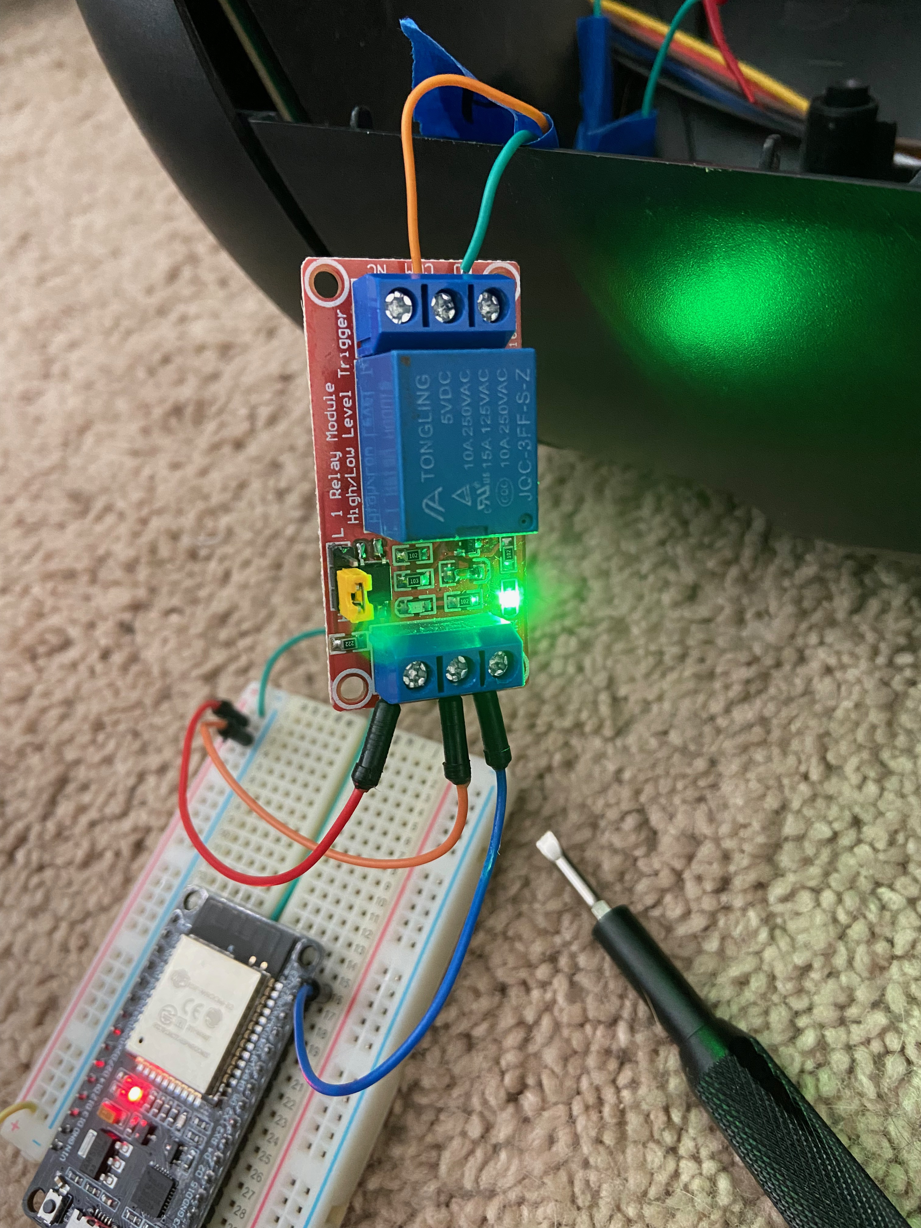
Next, I wanted to see if I could get it to work with a momentary switch. So I stripped and soldered a couple of wires onto the circuit board and a relay to the wires. I used some heat shrink tube to cover the solder points. I then turned on the fan and connected the wires together using the relay and a GPIO pin from the ESP32. The fan worked! So I had the basics to control the fan!
NOTE: Make sure to shield your controller to prevent arcs! I wrapped mine in electrical tape really well so that I could prevent fires. Yes! Fires!
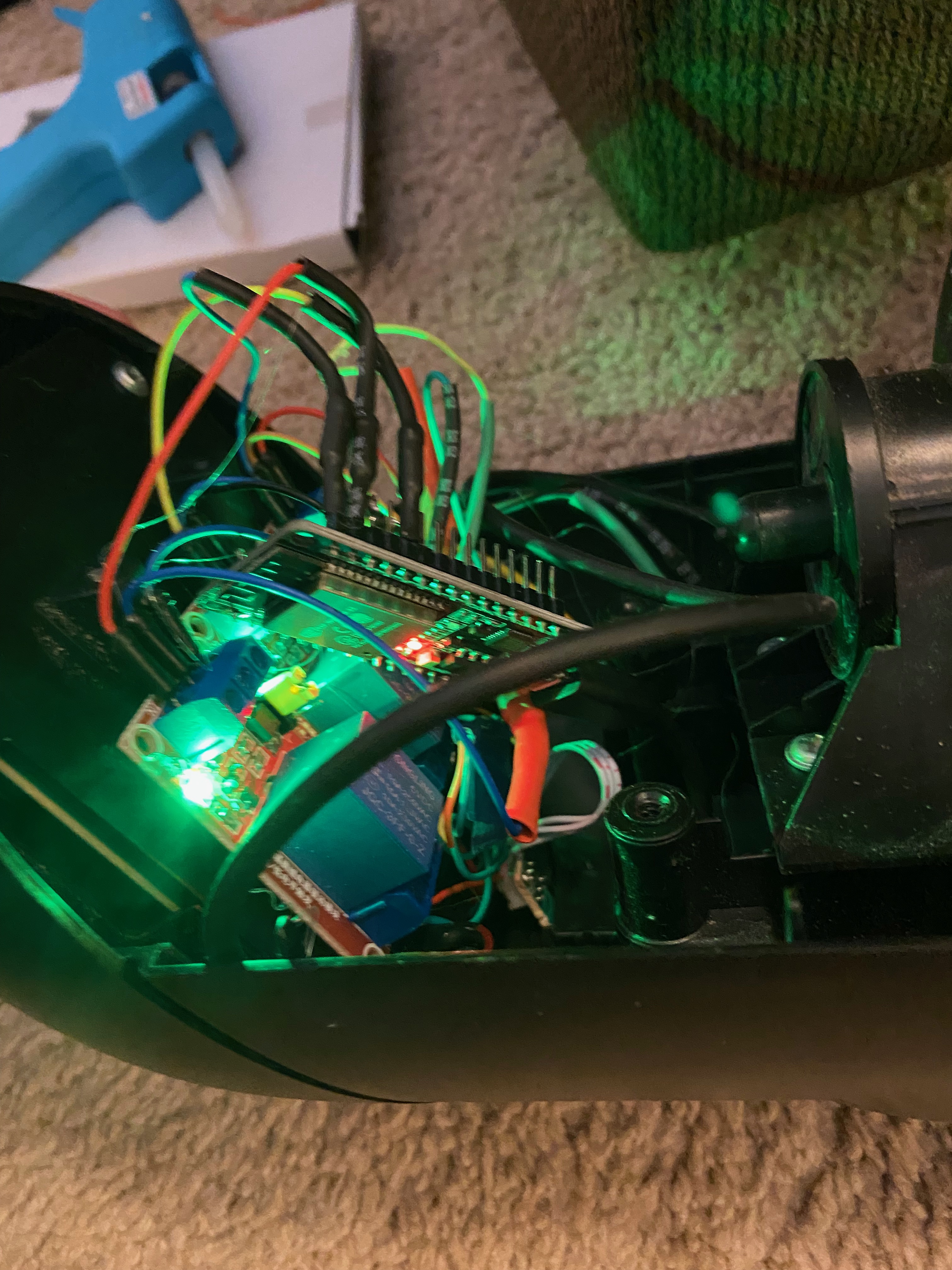
Making It Pretty
Since I am a software developer, I wanted it to look nice. I am going to use an NodeMCU ESP32 which is a small IoT device with a USB port and is programmable in ESPHome. I wanted it to fit easily into the existing housing so I routed all of the wires out of their chassis and into an empty area behind the control board. I was able to hook up the (3) relays to these and then connect it up to the ESP32. After I put it all together it still worked!
With this I was able to set a period of 500ms and trigger the momentary switch. This was highly successful and I was able to power on and off the device from Home Assistant!
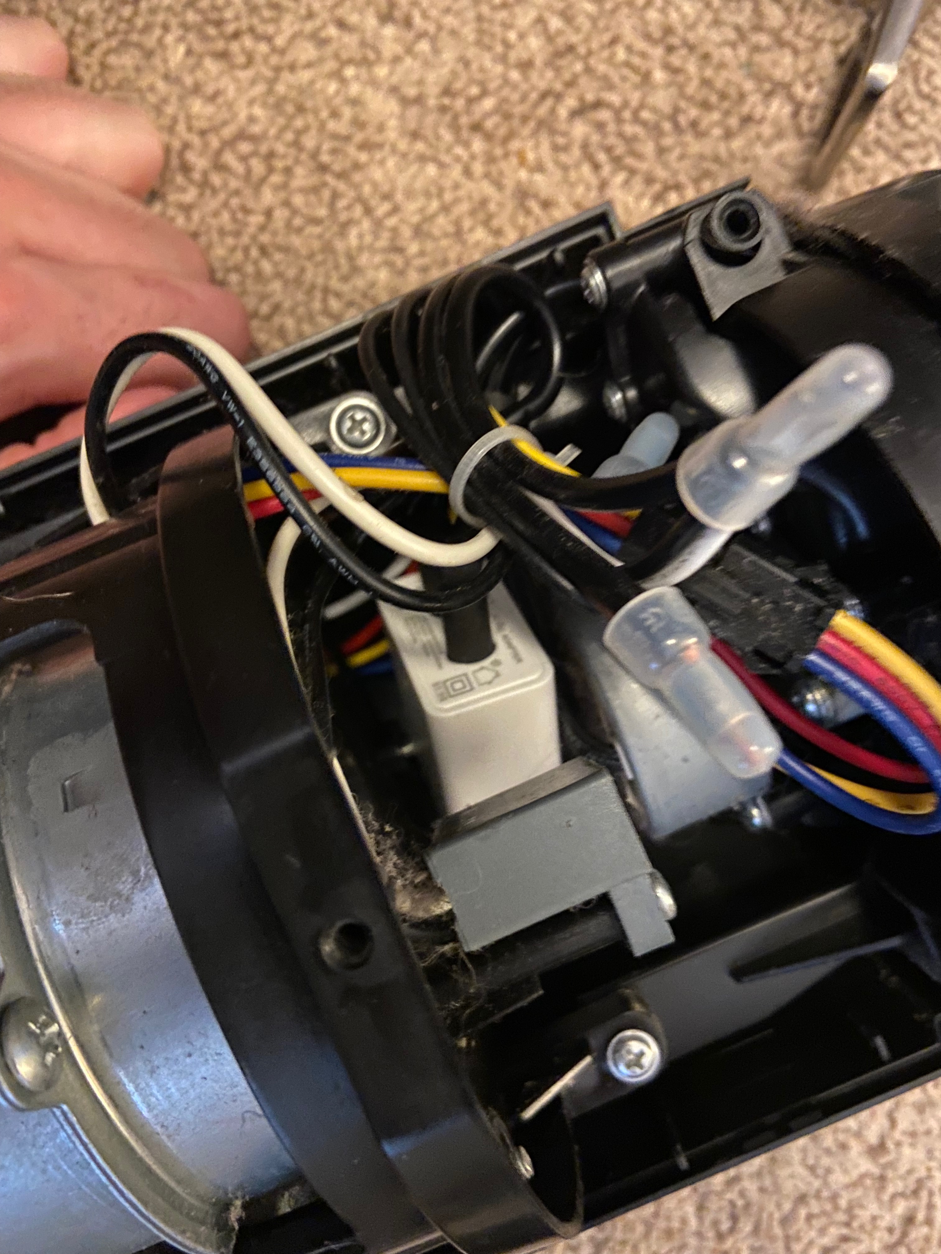
Getting Power
I needed to get the power from the mains to the ESP32. I was not sure how much power the ESP32 would need so I went with a little usb brick. This was just right for the board and super easy. All I had to do was splice the brick into the power and cover it really well with heat shrink tubing so that I won’t cause a short.
As you can see there is a small white power brick in the bottom of the fan and I then carried the usb cable up the fan along the path that the rest of the wires took.
Software
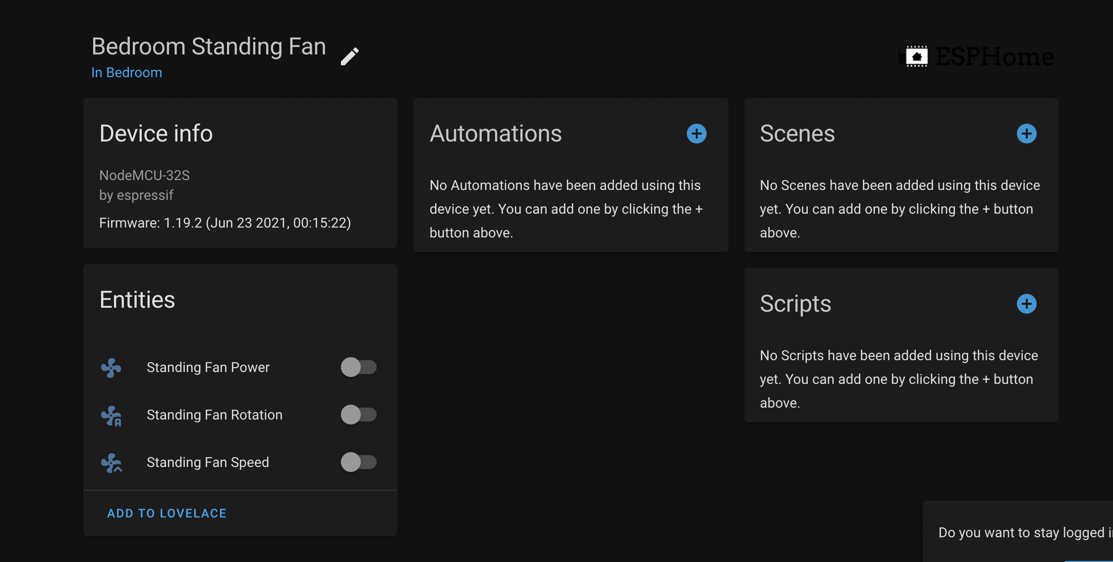
So it all worked! I did not need to do much to the software. I just modified my home automation code to use the new fan control. I then updated my code to be able to turn the fan on or off from Home Assistant. I also added the ability to turn the fan on and off with my voice by using Alexa.